QRP SSB Transceiver
This project was started with some inspiration and ideas from N6QW and DK7IH who both have lots of similar projects on their web sites and Youtube. I've also gathered some ideas from looking at the schematics for the famous K2 transceiver kit.
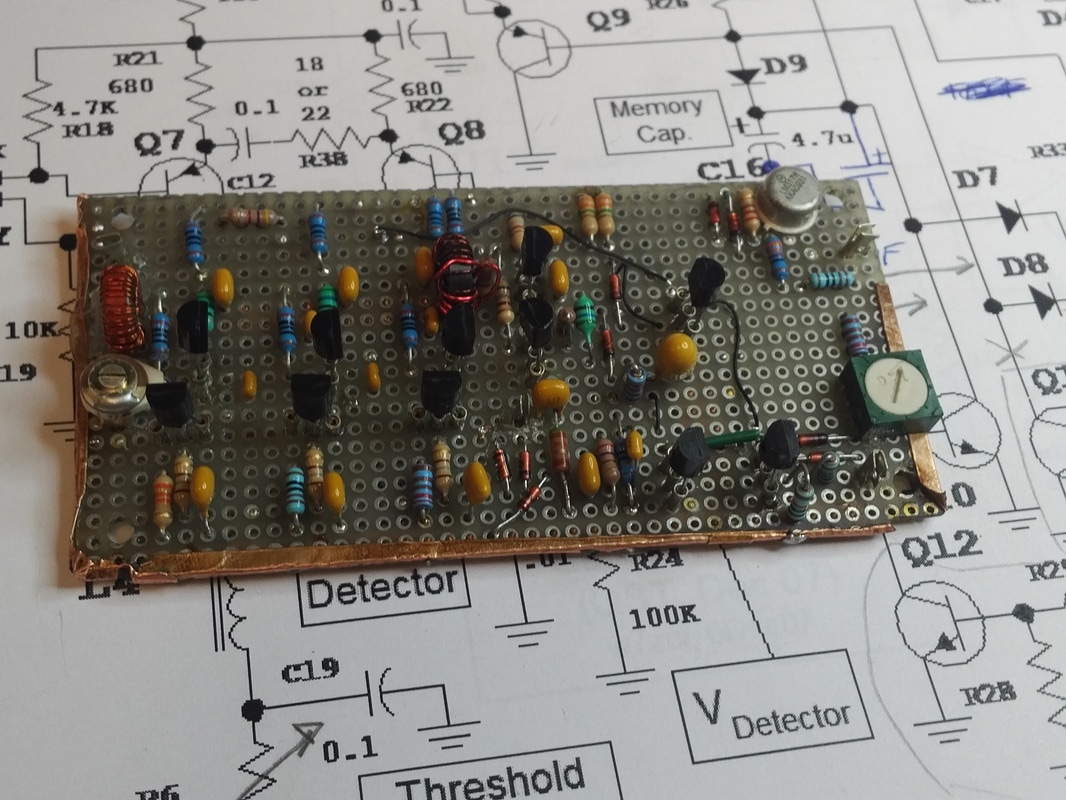
Anyway, here is the first module, as in N6QW's JABOM rig. This is the HYCAS IF amplifier which I've completed (but not yet tested) over the holiday weekend (5/27-29/2017). I followed the original schematics, though I changed the AGC time constant as described by Pete. I did leave out Q12 as I don't see any need to be able to disable the AGC, nor do I see the need for a mute switch (so the mute circuitry will be dedicated to the RX/TX control.) I left the original L1 in the circuit as I will be using a 9 mhz IF. I didn't have a molded 6.8uh choke, so I wound one on a T50-2 toroid. The other chokes are 56uh (didn't have any 47uh's in the junk box and the 56uh ones measured out closer to 53uh anyway). I built this on a scrap 2"x4" piece of PC perf board, and added some copper foil tape for ground buses. Flea clips were used for input/output terminals, and socket pins from molex IC sockets were used for transistor sockets. Most of the parts are on the top, but one resistor and one cap had to be placed on the bottom side as I ran out of wiring options on top. The TO-5 can in the corner is an LM317H regulator, an old surplus bit from the junque box.
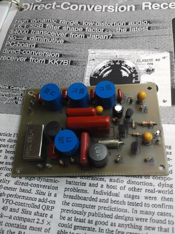
Rather than put the SBL-1 detector on the HYCAS IF board, I'm going to use the R1 module I built. This board was built on a PCB I designed and laid out myself using Eagle CAD, then etched with an iron on transfer sheet printed with a laser printer. The board has the circuitry up to the LPF, and leaves off the HPF, second AF preamp and power amp stages. I have the part for that and will probably bread board the remaining AF stages on a piece of perfboard.
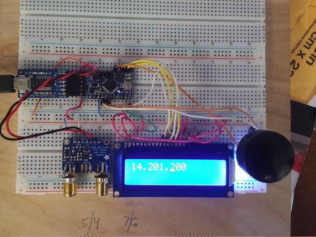
I plan on using an Adafruit Si5351A module as the VFO for the rig. I'm not sure if I'll use the other two outputs for anything. I have several surplus crystal filters that came with matching oscillator crystals, so I might not need to use the Si5351 as the bfo/carrier oscillator. Here is the breadboard setup I'll be using to develop the required software. The micro is an Sparkfun Arduino mini pro, and the display is an Adafruit 16x2 character. Under the knob is a common switch type encoder. Originally I was using an Adafruit feather 32u4 based development board, and a 128x64 0.96" OLED display, but I switched to the Mini Pro and the character LCD for a few reasons.
The OLED was just TOO SMALL! While that display was very sharp, and offered excellent graphics, I didn't want to need to have to wear my reading glasses to see it. The LCD is simply easier to read, and it doesn't require the graphics library that eats up almost 70% of the flash code space.
Usually people fit the Adafruit Si5351 module with SMA connectors, but those cost about $2.50 (or more!) each just for the female ones. I had a large number of old "RCA" phono connectors in the junque box, so that's what I'm using. I know they are supposed to be poor at RF, but at low power HF, they work fine.
The test sketch I'm running is N6QW's, modified to run with the 16x2 LCD. Changing the update increment moves the cursor under the corresponding digit. Now that I have the basic control of the Si5351 working, the next step will be to add band and mode switching. My plans are for a rig to cover 80, 40, and 20, and maybe I'll add 30 and 60 later on. Just what we need for the lack of sunspots.
I modified N6QW's Arduino sketch for the Si5351A to work with the Adafruit 32U4 feather board and quickly got the RF generator module working. Here is the first version of the Arduino sketch that runs this. A quick press on the encoder dial switch will toggle the increment (dial speed) to the next digit. You can tune in increments of 10hz, 100hz, 1khz, or 10khz in normal vfo mode. When in signal generator mode you can also tune in increments of 100khz, or 1mhz. A medium length click on the button will allow you to change bands with the dial. Currently 80,40 or 20. A long press changes the mode between USB, LSB, CW, or signal generator mode. In the latter, the displayed frequency IS the output of the generator. CW is currently the same as USB, but I'll probably add an offset between the transmitter and receiver frequency to account for the beat note (probably a 400hz shift). I also plan on adding a dial calibrator mode to set the Si5351 on frequency.
| si5351a.ino |
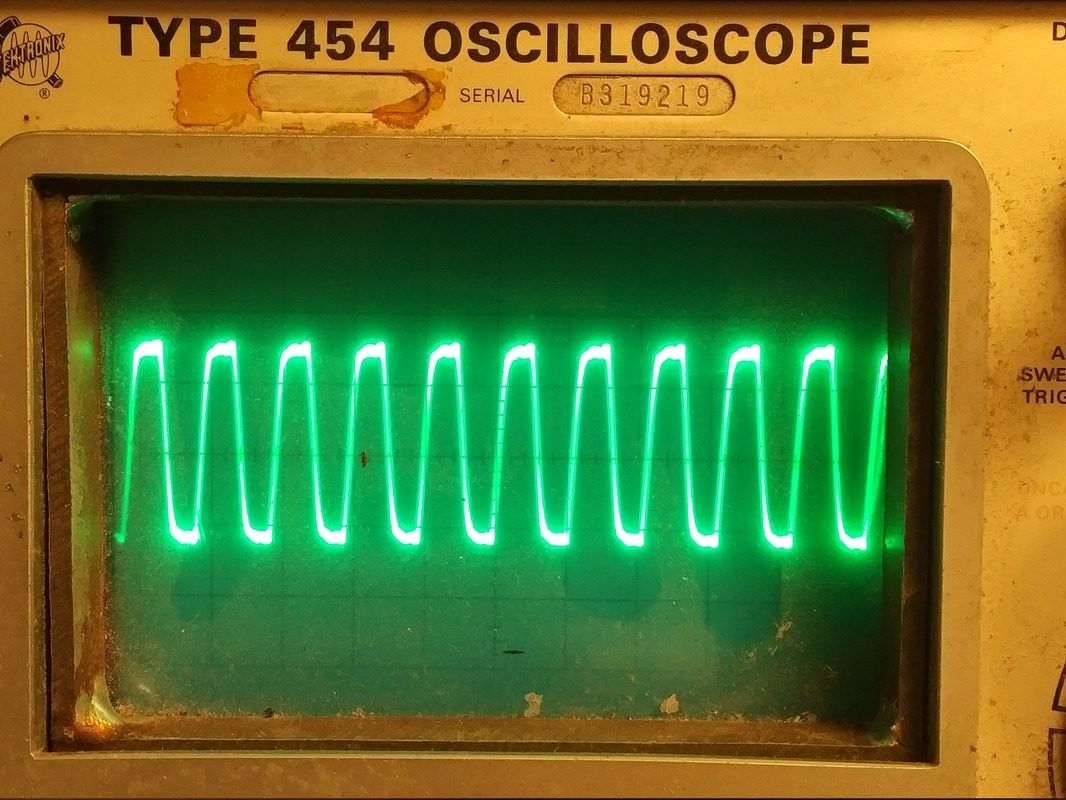
Here you can see the 19mhz output on my old Tek scope. It's mostly a square wave with a bit of ringing, typical of these programmable divider type chips. (I really should have cleaned off the scope screen before taking this picture!).
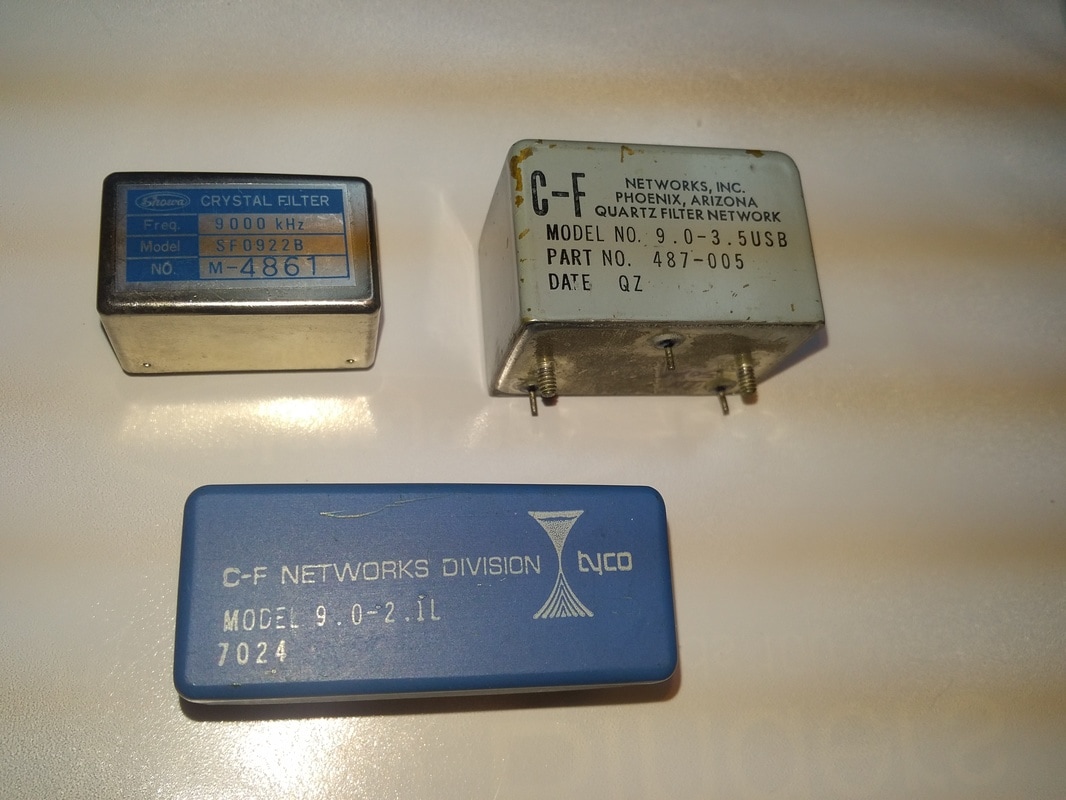
I have a few 9mhz crystal filters in the junque box to choose from. I have crystals that match the one on the upper left that can probably be pulled to match the one on the bottom. I also have some surplus 9mhz crystals that can probably be pulled to match the one in the upper right. All of these were surplus hamfest finds, the one in the upper right was a find at Dayton some years ago. I got a half dozen of those, they were made for the Gonset Sidewinder VHF rig, and have a 3.2 KHZ BW. A bit wide, but usable. The other two are standard 2.1-2.2khz BW types.
Not shown in the picture, I also have two filters removed from old CB rigs. One is a a 10.7mhz center frequency, the other is in the 11.25mhz region. Both are 2.5khz BW types from SSB rigs. I have matching carrier crystals for both of those.
At first it looked like the 10.7mhz filter would be good for a band imaging rig covering 40 and 20 meters with a single VFO in the 3.2-3.5mhz region. However, the second harmonic of the VFO falls into the 40 meter band and will cause a rather stong 'birdie' right in the middle band somewhere. If I use that filter, I'll use high side injection with a DDS or Si5351 signal source.
