Homebrew transceiver project based on Pic-A-Star
This started as a DDS signal generator controlled by an AVR micro controller. I built an R1 receiver board and was going to add a set of band pass filters and end up with a direct conversion receiver. Later, I could use the R1 as the product detector in a single conversion superhet receiver by adding a front end mixer and IF stage. I have several 9mhz IF filters that were purchased at the Dayton hamfest many years ago. Eventually, the plan was to add a transmitting mixer and balanced modulator to the receiver and end up with a transceiver. The front panel layout in the pictures below was based on this plan. I named the project the 'HB-100' following the Heathkit 'SB' series with the 'HB' part borrowed from the late W6TC and his famous receivers from the 1960's. I even started some of the metal work on a nice project box that has been in my junk box for about forty years.
The monkey wrench (or adjustable spanner on the east side of the 'pond) thrown into those plans was a design by G3XJP called the Pic-a-Star transceiver. What Peter actually came out with was a DSP IF system that could be added to any single conversion transceiver design. He added a bilateral H mode mixer first IF, bandpass filters and switching circuits to (almost) complete the transceiver chain. The missing bits were a transmitter power chain and audio amplifier. Most of the hams who built the Pic-a-Star transceiver settled on one (or both) of a pair of final amplifier designs also published in RadCom, being of 20 watts or 150 watts. The first using RF mosfets, the second conventional bipolar RF power devices.
G3XJP's design is a bit radical in that the front panel has ONLY TWO controls, a single knob in front of a rotary encoder and a 12 button keypad. The keypad can be used to enter commands, select bands or modes, and also to control the DSP processor options. The knob can function as the VFO control, or be assigned to any other variable function such as the volume control, power adjust, etc... While it does make for a VERY clean panel, it also is quite unusual! There is an alternate front panel design called the TrxAVR which makes use of an Atmel atmega processor instead of a PIC. This design has variations using graphical LCD's (with and without touch screens), or multi line character LCDs. It also provides multiple rotary encoders to adjust assigned DSP options so the panel more closely resembles a conventional transceiver.
I decided to build the Pic-a-Star as closely as possible to Peter's design. I obtained a TrxAVRB PC board from Glenn, PK3VE which I plan on using instead of the Pic-n-Mix (though I might build the Pic-n-Mix controller initially for testing). I have a working DDS-60 which is functionally identical to the DDS initially used in the 'Star that could be used. I plan on building up a DDS based on the AD9951 for the final unit.
I plan on using the PA3AKE band pass filters instead of Peter's design, mostly because the toroids were easier to get (and cheaper) than the adjustable coils. The PA3AKE filters should, in theory, also deliver better performance. I won't build the filter unit exactly as per the PA3AKE plans, as I need to modify the boards to fit and I'm thinking of sub'ing Peter's FST switches for the relays. I'll also add trimmer caps for aligning the filters, a bit easier to adjust than spreading or squeezing the coil windings.
I also obtained a PC board from Glenn for an experimental version of the 'magic roundabout' mixer that uses a pair of FSA3157's instead of the usual FST3125. This design is also based on the work of PA3AKE. It will also end up in my unit.
So far I've etched the pc boards for the DSP section of the 'star and have some parts on order. This isn't going to be a quickie project. I'll be posting pictures and details as things progress.
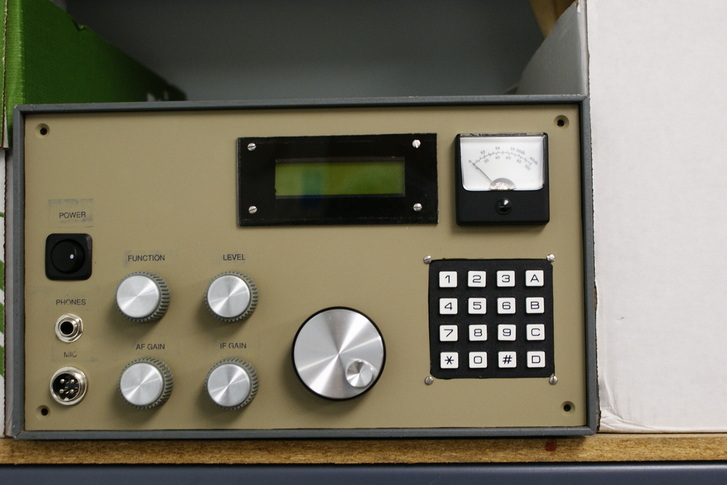
This is the front panel of the transceiver as it now stands. I just finished cutting out all the openings and holes for the parts, re-painted the panel, applied some labels and mounted the controls. The labels were printed using a laser printer onto iron on transfer sheets normally used for making PC boards. The transfers didn't work as well onto a painted surface as they do onto bare copper. It'll do for now, later I'll probably buy one of those label making machines and replace the markings with stick on tape labels. The cabinet has been sitting in my junk box for about 40 years (I found it at Leed's Radio on Canal Street NYC in the 1970's). The panel isn't screwed into the cabinet i this photo just friction fit. I latter stripped the paint off the cabinet and re-painted it (the 40 year old paint was peeling off and has became gooey to the touch). The color scheme is now a light / dark olive drab "military" look.
The display is a 2 line, 16 character LCD. The bezel in front of the LCD was made from a piece of plexi-glass cut to size, masked and spray painted on the back side. None of the controls are wired up yet. The AF GAIN, IF GAIN, and LEVEL controls are standard pots, the FUNCTION control is a low resolution rotary encoder with push button switch. The tuning knob is a high resolution rotary encoder. The function knob will be eventually be used to control functions within a DSP processor to be added later. The 4 pin MIC jack will probably be replaced by an 8 pin Icom / Kenwood style jack if I can find one. Not all of the controls will get used right away, but I wanted to do all the metal work up front now.
UPDATE:
The control layout of the panel was based on a different design than Pic-a-Star and I suspect I will be making a new panel or re-drilling this one and changing some things around. The 2 line x 16 character display will be replaced by a graphic LCD to go with the TrxAVR controller. I have a nice 192x64 display that can replace the 128x64 unit already designed into the TrxAVR software. With a few minor changes in the code the wider display will work, and I can adjust the firmware to make use of the extra display real estate.
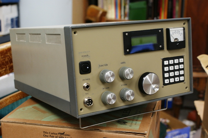
Here's a view of the completed panel fitted into the cabinet before I repainted the cabinet.
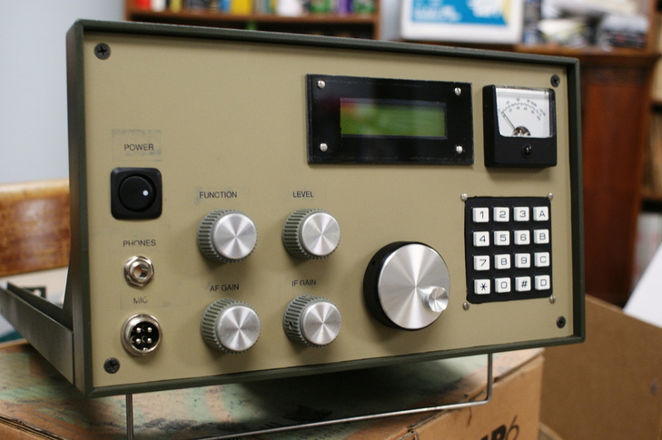
Here is the front panel mounted in the cabinet after re-painting the cabinet.
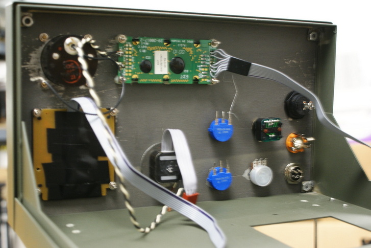
This is the backside of the front panel. Nothing has been wired up yet.
UPDATE: The control layout and display are going to change as I noted above.
UPDATE: The control layout and display are going to change as I noted above.
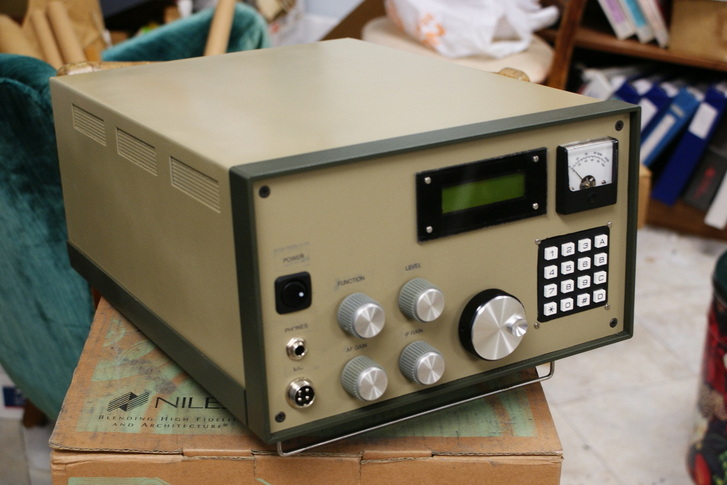
Repainted cabinet. Compare with the original photo above.
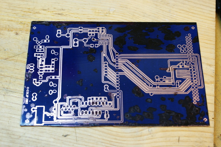
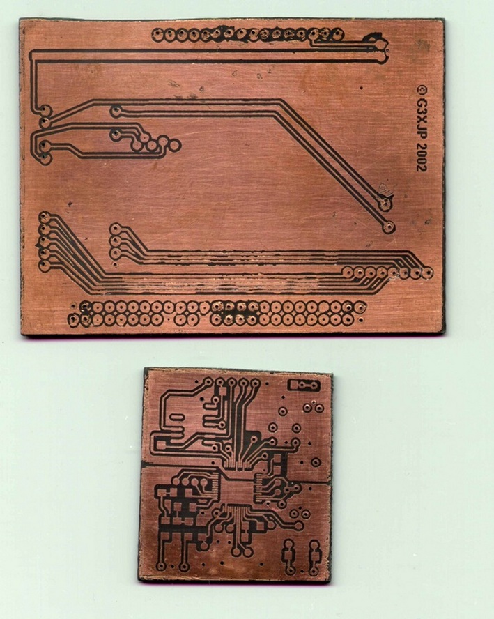
Here is the etched boardset for the Pic-a-Star DSP. The motherboard came out quite potmarked and will need some repair of the tracks. I will probably remake this one again. The DSP processor and Codec boards look a lot better. There is one missing track on the front of the processor board and the Codec board has a few shorts between tracks. I can fix the latter with an xacto knife under a microscope. The missing track can be repaired with a jumper wire.
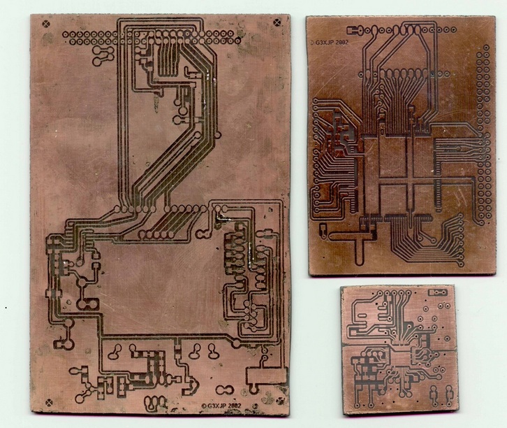
Here are the back sides of the processor and code boards. (oops didn't flip the codec board over!) Both have some track shorts that will require the knife treatment.